
Structural Design
When designing a new project, it’s crucial design engineers consider the structural design and what materials to use for it. The type of material selected will depend on factors such as the project’s purpose, weight, cost, strength, and rigidity required. For instance, aircraft design may prefer aluminium or plastic due to weight while steel could be the most cost-effective for high strength structures. Regardless of the selected material, design engineers must systematically investigate and ensure it can carry the load, withstand stress, and be stable. A well engineered design will significantly reduce the risk of costly failure by accounting for the demands on the structure and selecting materials accordingly. Therefore, carefully considering materials from the start of a project will ensure a safer, more economical, and durable structure.

Stress and Strain
Stress and strain are vital for design engineers to consider in structural design as they impact safety. Engineers must calculate the stress to ensure it can withstand forces, and they must consider properties and how it behaves in different conditions. It is a complex engineering discipline that needs knowledge of physics, mechanics, and materials science to measure loads, divide by the area and obtain stress levels. Understanding these calculations is vital for ensuring structures don’t fail.
Finite Element Analysis
Software development has improved modern engineering by enabling the use of Finite Element, static stress analysis and 3D design. These tools help ensure product quality and reduce the risk of defects and failure by allowing design, analysis and testing to be performed before production. For more information, refer to the links below for useful websites.
Image of The Forth Rail Bridge by dassel from Pixabay
Mechanical Properties
Stress is defined as the force applied per unit area of a material. On the other hand, strain is the deformation or change in size and shape of a material due to stress. To do stress analysis on materials, engineers need to have a clear understanding of the mechanical properties of these materials. These properties are usually provided by material manufacturers and include cross-section sizes, tensile and compressive strength, and shear strength.
By using recognised equations, engineers can estimate the stress and strain that a material undergoes when it is subjected to load. Estimating these values is critical for designing durable and reliable structures that Design engineers consider structural design that can withstand external forces. Therefore, it is essential to have accurate and up-to-date information on the mechanical properties of a material. To obtain a value of both stress and strain, use the following equations shown below:

The graph opposite shows a stress strain curve produced when a material is subject to a tensile test. The Yield Point shows when the stress on the material causes it to deform. This identifies the end of the elastic behaviour and the beginning of plastic behaviour of a material. Some materials undergo a sudden extension without an increase in load at this stage. To calculate the yield stress at this point, divide the load at yield by the original cross-sectional area. In the elastic range, the material returns to its original length. If the material passes the yield point, it enters the plastic range. In this range, the material undergoes permanent extension. Once it passes the point of maximum tensile strength, it continues to extend with a reducing load. The stress increases up until the material fractures.

Design Codes
Scotland, like many countries, has Building Standards providing guidance to ensure good standards under the Building (Scotland) Regulations 2004. Also, the Scottish Government issues technical handbooks to assist with achieving these standards. Certainly, engineers designing structural systems in Scotland need to be familiar with these standards. The design codes in the technical handbooks reference the European Standards for structure (Structural Eurocodes).

Any new structure or building design must comply with the details set out in the Eurocodes. The table below lists the Eurocodes:
Eurocodes | Details |
Basis of structural design | |
1 | Actions on structures |
2 | Design of concrete structures |
3 | Design of steel structures |
4 | Design of composite steel and concrete structures |
5 | Design of timber structures |
6 | Design of masonry structures |
7 | Geotechnical design |
8 | Design of structures for earthquake resistance |
9 | Design of aluminium structures |
Worked Example
The following is an example of how to find the maximum bending stress on a specified beam:
It is based on a British Steel section serial size 356 x 171 x 67 Universal beam. This has a mass of 67.1 kg per metre. The drawing opposite shows the cross-section of this Universal beam (UB).
Calculations
To obtain the maximum bending stress requires using all the equations below. In order to obtain the correct units.
The Area Equations. The cross-sectional area of the universal beam allows estimation of normal stress, to allow estimation of the maximum bending moment, requires estimation of the second moment of area on the x-axis. Finally, the equations also obtain the distance required between the point load and neutral axis.
Bending Moments. In the Mmax equation, the value of “F” is the load applied to the beam. The a and b values are the distances of the point load from the the support “A” and “B”. To find the maximum allowable bending stress the σy is the yield strength of hot rolled steel and is divided by the factor of safety “FOS” in this case 5. To determine the maximum bending stress, “y” is the distance to the point load from the neutral axis and “L” is the length of the beam.
Stress Strain. The normal stress “σ” takes, “F” the maximum load applied to the beam and divides it by “A”, the cross-sectional area of the beam. The strain on the beam is determined by the maximum bending stress “σb” divided by Young’s modulus “E”.
Deflection and Extension. The maximum load “F” multiplied by the length of the beam “L” cubed and divided by 48 multiplied by the Young’s modulus “E” multiplied by the second moment of area on the x-x axis Ixx gives the maximum deflection of the beam “δmax“. To obtain the maximum extension of the beam “ΔL” multiply the length of the beam “L” by the strain on the beam “ɛ”.
Sources Used and Further Reading
Properties of the Material
Young’s modulus of elasticity indicates how easily a material such as in the UB could bend or stretch. Dividing the maximum stress by the strain, produces the Young’s modulus and indicates the stiffness of the material. For this example, the choice selected is a Young’s modulus of E = 210 GPa.
The Yield Strength indicates the elastic limit of the material. If the stress exceeds the Yield Strength, then the material will deform permanently. If the stress applied does not exceed the Yield Strength, then the material will return to its original shape. For this example, the chosen Yield Strength used is σy = 250 Mpa. A Factor of Safety (FOS) of 5 applied to the calculations as a safeguard.
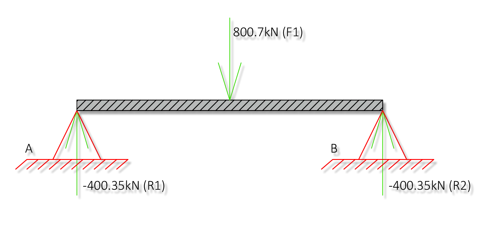
The length of the beam is L = 2.0 metres long, with a support at each end. A load applied of F = 800.7 kN to the centre of the beam, as shown in the sketch:

PDF Files
Click to open PDF file – This sheet provides how to calculate the stress, bending moment, strain, maximum deflection and maximum extension of a Circular Hollow Section. The CHS is supported at both ends and has a point load applied.
Click to open PDF file – This sheet demonstrates how to calculate the stress, bending moment, strain, maximum deflection and maximum extension of a Universal beam. The UB is supported at both ends and has a point load applied.
Click to open PDF file – This sheet demonstrates how to calculate the stress, bending moment, strain, maximum deflection and maximum extension of a Universal beam. The UB is supported at both ends and has two equidistant point loads applied.
Click to open PDF file – This sheet demonstrates how to calculate the stress, bending moment, strain, maximum deflection and maximum extension of a Universal beam. The UB is supported at both ends with distributed loading applied.


